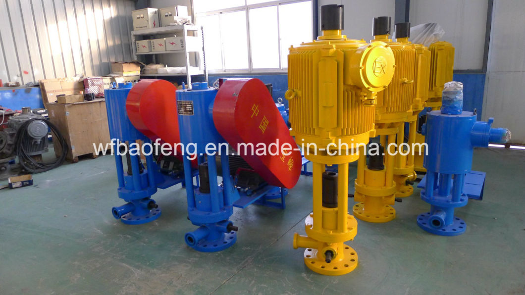
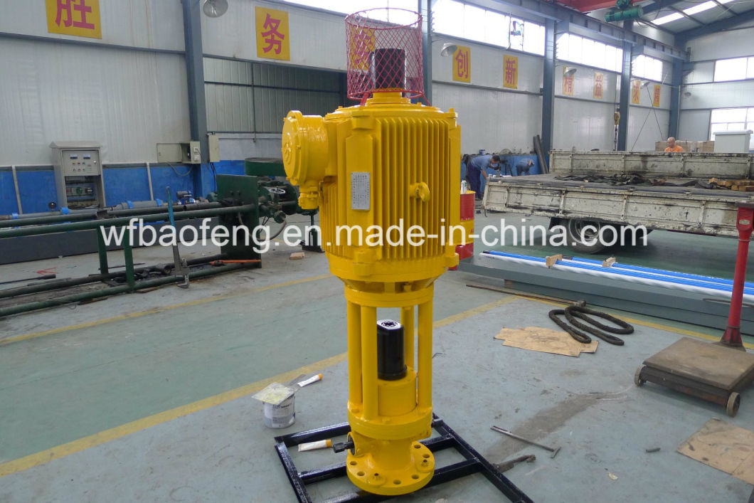
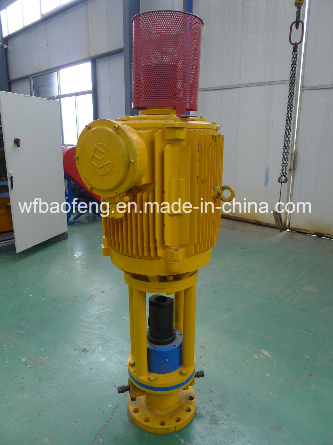
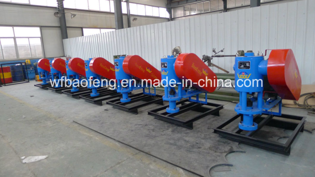
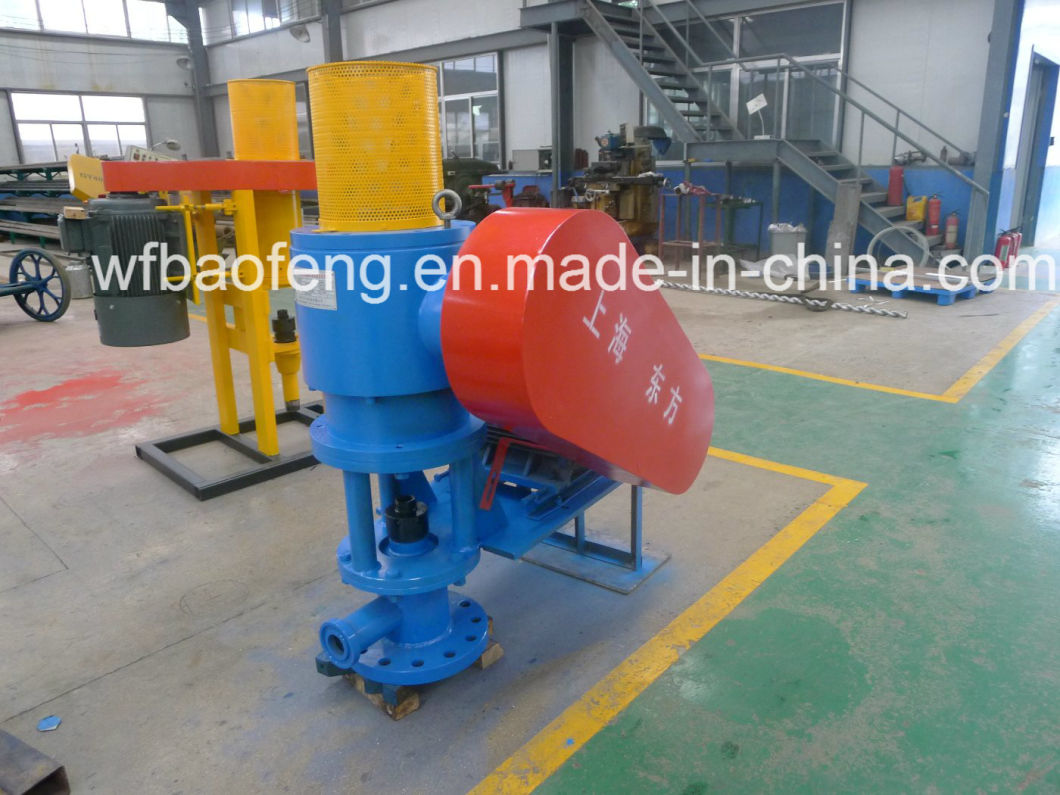
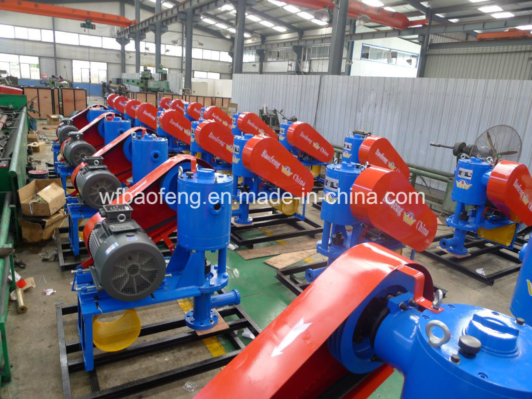
Progressive Cavity Pump System (PC Pump)
Progressive Cavity Pump (PC Pump) System is a new kind of oil production equipment. The system consists of Surface Drive Head and Downhole part, electrical control cabinet.
Features:
PC Pump has been widely used in oil fields at home and abroad and plays an important role in oil production.   The PC Pump can be used for low viscosity crude oil, also for heavy oil, high freezing point oil, high wax oil, high sand oil and high gas oil. There is a trend to replace the large heavy pumping units in shallow well and middle-deep well. Â
Advantages:
It has advantages of one-time low investment, high oil production efficiency, low energy consumption, simple structure, and easy operation, installation and maintenance.
Â
|
Model |
Rated voltage (V) |
rated torque   (N.m) |
rated rotary speed   (r/min) |
rated power   (KW) |
ratio η(%) |
speed adjust range   (r/min) |
| LBQZ11 | 380 | 525 | 200 | 11 | 90.5 | 15-200 |
| LBQZ15 | 380 | 716 | 200 | 15 | 90.5 | 15-200 |
| LBQZ18.5 | 380 | 883 | 200 | 18.5 | 91.5 | 15-200 |
| LBQZ22 | 380 | 1051 | 200 | 22 | 91.5 | 15-200 |
| LBQZ30 | 380 | 1433 | 200 | 30 | 92.5 | 15-200 |
| LBQZ37 | 380 | 1767 | 200 | 37 | 93 | 15-200 |
PC Pump Setting Parameters
| Setting depth(m) | 500 | 600 | 700 | 800 | 900 | 1000 | 1100 | 1200 |
| Lifting distance (mm) | 550 | 650 | 750 | 850 | 950 | 1100 | 1200 | 1300 |
GLB series of PC Pump Parameters
|
Model |
Length (mm) |
Maxi. Diameter (mm) |
Rotor screw (in) |
Stator upper screw(in) |
Stator lower screw(in) |
Rod rate (rpm) |
Theoretical dairy flow(m3/d) |
Applicable tubing(in) |
Sucker rod(in) |
Head(m) |
| GLB\10/35 | 2940 | 90 | 15/16″ | 2-7/8″ | 2-7/8″ | 60-150 | 1-4 | ≥73 | 7/8″ | 1000-1400            |
| GLB\28/40 | 3650 | 90 | 1-3/16″ | 2-7/8″ | 2-7/8″ | 60-150 | 3-6 | ≥73 | 7/8″ | 1200-1600 |
| GLB\40/12 | 1550 | 90 | 1-3/16″ | 2-7/8″ | 2-7/8″ | 60-150 | 4-9 | ≥73 | 7/8″ | 600-800 |
| GLB\40/14 | 2200 | 90 | 1-3/16″ | 2-7/8″ | 2-7/8″ | 60-150 | 4-9 | ≥73 | 7/8″ | 400-600 |
| GLB\40/21 | 2330 | 90 | 1-3/16″ | 2-7/8″ | 2-7/8″ | 60-150 | 4-9 | ≥73 | 7/8″ | 700-1000 |
| GLB\40/42 | 4670 | 90 | 1-3/16″ | 2-7/8″ | 2-7/8″ | 60-150 | 4-9 | ≥73 | 7/8″ | 1200-1800 |
| GLB\50/21 | 2380 | 90 | 1-3/16″ | 2-7/8″ | 2-7/8″ | 60-150 | 5-10 | ≥73 | 7/8″ | 700-1000 |
| GLB\75/14 | 2140 | 90 | 1-3/8″ | 3-1/2″ | 2-7/8″ | 60-150 | 6-15 | ≥73 | 7/8″ | 400-600 |
| GLB\75/21 | 2200 | 108 | 1-3/8″ | 3-1/2″ | 2-7/8″ | 60-150 | 6-15 | ≥73 | 1″ | 700-1000 |
| GLB\75/40 | 4410 | 108 | 1-3/8″ | 3-1/2″ | 2-7/8″ | 60-150 | 6-15 | ≥73 | 1″ | 1200-1600 |
| LB\120/18 | 3000 | 108 | 1-3/8″ | 3-1/2″ | 2-7/8″ | 60-150 | 10-25 | ≥73 | 1″ | 500-800 |
| GLB\120/21 | 2932 | 108 | 1-3/8″ | 3-1/2″ | 2-7/8″ | 60-150 | 10-25 | ≥73 | 1″ | 700-1000 |
| GLB\120/27 | 4428 | 108 | 1-3/8″ | 3-1/2″ | 2-7/8″ | 60-150 | 10-25 | ≥73 | 1″ | 800-1000 |
| GLB\120/36 | 5865 | 108 | 1-3/8″ | 3-1/2″ | 2-7/8″ | 60-150 | 10-25 | ≥73 | 1″ | 1100-1400 |
| GLB\120/40 | 5900 | 108 | 1-3/8″ | 3-1/2″ | 2-7/8″ | 60-150 | 10-25 | ≥73 | 1″ | 1200-1600 |
| GLB\165/35 | 5650 | 114 | 1-3/8″ | 3-1/2″ | 2-7/8″ | 60-150 | 14-36 | ≥73 | 1″ | 900-1300 |
| GLB\190/33 | 5650 | 117 | 1-3/8″ | 3-1/2″ | 2-7/8″ | 60-150 | 15-40 | ≥73 | 1″ | 900-1300 |
| GLB\200/27 | 5650 | 114 | 1-3/8″ | 3-1/2″ | 2-7/8″ | 60-150 | 17-42 | ≥73 | 1″ | 800-1000 |
| GLB\300/21 | 4850 | 114 | 1-3/8″ | 3-1/2″ | 2-7/8″ | 60-150 | 25-60 | ≥73 | 1″ | 700-1000 |
| GLB\300/26 | 6000 | 114 | 1-3/8″ | 3-1/2″ | 2-7/8″ | 60-150 | 25-60 | ≥88.9 | 1″ | 700-1000 |
| GLB\300/33 | 6200 | 117 | 1-3/8″ | 3-1/2″ | 2-7/8″ | 60-150 | 25-60 | ≥88.9 | 1″ | 800-1200 |
| GLB\420/20 | 4820 | 117 | 1-3/8″ | 3-1/2″ | 2-7/8″ | 60-150 | 35-70 | ≥88.9 | 1″ | 700-1000 |
| GLB\500/14 | 3380 | 117 | 1-3/8″ | 3-1/2″ | 2-7/8″ | 60-150 | 40-80 | ≥88.9 | 1″ | 600-800 |
| GLB\500/21 | 5060 | 117 | 1-3/8″ | 3-1/2″ | 2-7/8″ | 60-150 | 40-80 | ≥88.9 | 1″ | 700-1000 |
| GLB\600/18 | 7122 | 117 | 1-3/8″ | 3-1/2″ | 2-7/8″ | 60-150 | 85-130 | ≥88.9 | 1″ | 500-900 |
| GLB\230/2-30 | 6200 | 117 | 1-3/8″ | 3-1/2″ | 2-7/8″ | 60-150 | 20-50 | ≥88.9 | 1″ | 900-1200 |
| GLB\450/2-24 | 6520 | 117 | 1-3/8″ | 3-1/2″ | 2-7/8″ | 60-150 | 39-97 | ≥88.9 | 1″ | 700-1000 |
| GLB\800/2-16 | 5020 | 117 | 1-9/16″ | 3-1/2″ | 2-7/8″ | 60-150 | 70-173 | ≥88.9 | KG36″ | 500-700 |
| GLB\800/2-24 | 7120 | 117 | 1-9/16″ | 3-1/2″ | 2-7/8″ | 60-150 | 70-173 | ≥88.9 | KG36″ | 700-900 |
| GLB\1200/2-16 | 6640 | 117 | 1-9/16″ | 3-1/2″ | 2-7/8″ | 60-150 | 103-260 | ≥88.9 | KG36″ | 600-800 |
| GLB\1400/2-16 | 7420 | 117 | 1-9/16″ | 3-1/2″ | 2-7/8″ | 60-150 | 120-302 | ≥88.9 | KG36″ | 600-800 |
| GLB\1600/2-14 | 7420 | 117 | 1-9/16″ | 3-1/2″ | 2-7/8″ | 60-150 | 138-345 | ≥88.9 | KG36″ | 500-700 |
| GLB\1800/2-14 | 7470 | 117 | 1-9/16″ | 3-1/2″ | 2-7/8″ | 60-150 | 155-388 | ≥88.9 | KG36″ | 500-700 |
| GLB\2500/2-8 | 7470 | 117 | 1-9/16″ | 3-1/2″ | 2-7/8″ | 60-150 | 216-540 | ≥88.9 | KG36″ | 400-600 |
| GLB\3000/2-8 | 7680 | 117 | 1-9/16″ | 3-1/2″ | 2-7/8″ | 60-150 | 260-648 | ≥88.9 | KG36″ | 400-600 |
|
The pipeline heat shrink coating system designed for corrosion protection of straight pipes, fittings, bends, elbows and other irregular configurations. It consists low pre-heat modified bitumen sealant adhesive and thick-wall irradiated cross linked polyolefin. When heated the backing layer shrinks and the adhesive flows and forms a reliable corrosion protection seal onto metal and adjacent coating surfaces. It cons Heat Shrink Tape It installed by wrapping the tape on the pipe joints ,fittings ,bends ,elbows etc .After the shrinking of the tape ,the closure patch should be installed onto the overlap of the tape. heat shrinkable sleeves,heat shrinkable tape Jining Xunda Pipe Coating Material Co.,Ltd , https://www.alta-altene.com |