High-rise residential cable television system solution Hemudu Intelligent Building System Solution Pavilion Along with the accelerating urbanization process, the high-rise building is becoming more and more obvious. In order to lay cables between the floors, it is necessary to independently set the weak electric well in each unit. With the rapid development of urban construction in China, high-rise buildings have become an important landmark of the city. Compared with ordinary buildings, high-rise buildings have certain characteristics in many aspects. For example: how to install a cable television network. This article describes some of the methods and experiences of cable television network design for high-rise residential buildings.
In the intelligent building engineering design, the cable television receiving system is a basic system that is universally set to meet people's functional requirements. The system will follow the improvement of people's requirements for television viewing quality and the development of cable television technology in application and design technology. Constantly improve. Judging from the current construction of China’s intelligent buildings, this system has become an indispensable part. TV culture is the most popular leisure culture for Chinese people. Watching TV has become the main leisure and entertainment method for urban and rural residents. Cable television signals can transmit high-quality television signals to millions of households and use people to enjoy TV as a recreational and entertainment resource. As a result, cable TV access communities, families, and dormitories have naturally become a requirement for urban and rural residents in China. One of the prerequisites.
The cable television system is an image transmission system that uses coaxial cables for broadband transmission. It can also broadcast television signals and television signals from local cable networks through the source equipment (video recorders, Blu-ray DVDs, cable set-top boxes, etc.) in buildings. The system delivers high quality television image signals to user terminals on the floor through a coaxial cable distribution network.
At present, the cable television network is the largest platform for domestic broadcast and television public information networks. It has many irreplaceable advantages, such as abundant frequency resources, a large number of users and stability, rich information content, and fast transmission speeds such as b2b.homedo.com. With the accelerating process of urbanization, the number and the number of high-rise buildings in China have shown an upward trend. This article focuses on the analysis and design of cable television distribution networks for high-rise residential buildings.
1, network distribution form design
(1) When designing the distribution network, the allocation method should be adopted as much as possible, and branching methods should be avoided. The design bandwidth should be 5-750MHz, in order to reduce the line loss, the cable between the amplifier and each layer can use SYWV75-9, SYWV75-12 cable, the reason is:
1 In this way, the number of splitters that pass through each user port after upgrade to bidirectional transmission is the same, which facilitates the debugging of the CableModem return level. This is common to the return of HFCs or the transmission method of Skynet. It is good;
2 For higher-level users, there aren't many splitters in the middle, and the chance of failure is much less;
3 In this way, although the amount of cable used is a little larger, the efficiency of the amplifier is improved a lot because the level of the output of the amplifier is not enough to satisfy the requirement after passing through more than 10 stages of splitters.
(2) The main line entering a high-rise building is generally buried in the main amplifier box through the SYWV75-9 cable or cable. For high-rises up to 30 levels, a single-stage amplifier is generally sufficient, and light may be used when conditions permit. Receiver direct output, amplifier box is generally set on a layer, easy to maintain; for more than 30 layers of high-level should consider multi-stage amplifiers, secondary amplifiers should be able to provide enough levels for the highest level of users, and the installation of high and we must try to Low design principle.
(3) Each layer distributor distributes the television signal into the intelligent information box of each suite, and then distributes the information box through the distributor to the user box in the suite. If more than one user terminal is installed in the suite, each terminal should be designed to independently lead to the intelligent information box through its own embedded pipe, and should not be designed to connect to each user's terminal in series through a built-in pipe. In short, try to avoid using multiple splitters.
(4) Each distributor box and the bottom amplifier box are placed outside the weak electric well, and the installation height of 1.8m is appropriate. The placement of the user's terminal is generally for the user's terminal in the living room to be placed on the opposite side of the door or diagonally opposite the corner of the wall. The distance is 0.5m, and the installation height is 0.25m. The user's terminal in the bedroom is generally placed on the side of the door, that is, on the opposite side of the bunk wall, the distance from the inside corner is lm, and the height is 0.25m.
2, centralized distribution form design
Centralized distribution, as the name implies, means that a television signal distribution centralizer is added to the middle floor of a building in a building. The cable TV cables of all users in the building are separated from the device box in the middle floor (equivalent to a household in the power supply bureau). A table), one cable per household, do not interfere with each other. The signal input lines of the two sides of the unit directly lay cables from the middle floor to the two sides of the building's middle unit. The wiring in the corridor is the same.
The advantages of centralized distribution are:
1) The branching device is located on the middle floor of the building, with the lowest line failure rate and the least failure point;
2) The television signal is easy to maintain;
3) The highest true line security;
4) The signals of each user are basically the same, which is conducive to the future development of digital television and two-way services.
Main trunk lines entering high-rise buildings generally adopt dark pipe laying methods and enter the unit through SYWV75-9 cables or optical cables.
The following section uses the high-level of a certain district as an example to introduce the principles and advantages of centralized distribution. The district has built 3 buildings, each with 18 units and 4 units. It is a two-family unit with a total of 152 users per building. It is now adopting a centralized distribution design method to design it.
According to SARFT's design requirements, each optical node should not have more than 200 users in its guiding ideology. It designs a total of 3 optical nodes for the community and uses optical nodes to directly cover users. In order to facilitate future overhaul, the light machine should be designed to be placed in the front floor landing box. The user should use the SYWV75-9 cable for the cross unit cable. In each unit, a six-tier, one-in-one approach is used to use a 12-branch splitter to consolidate all 12 subscribers' cable television lines together. This requires 300*400* design in the 3, 9 and 15 layer pipeline wells. The 150mm splitter box is used to install splitters and hubs, and then goes through 12 splitters and uses -5 cables to directly enter the users. The designed network system is shown in Fig.1 and Fig.2.
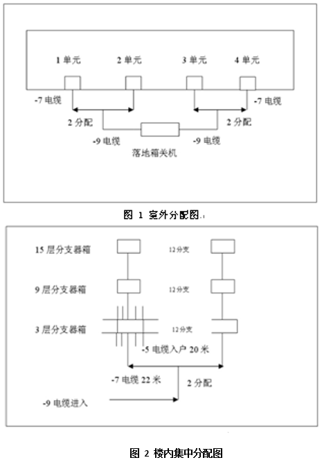
The SYWV75-9 cable is used to feed the unit cable, the distributor and the splitter, and the connection between the splitter and the splitter is -7 cable, and the cable for entering the home is the SYWV75-5 cable. The TV signal entering the corridor is 104dB, the height of the storey is 3 meters, and the subscriber line is 20 meters to calculate the signal level of the most remote user in each branch.
Layer 3 splitter users are users from 1 to 6 floors. The distance between the distributor on the first floor and the 12th branch on the third floor is 22 meters with an attenuation of -3.5dB; the users on the first and sixth floors are the users with the furthest distance from the branch on the third floor, and the distance from the branch box is 30 meters. The attenuation is -6dB, then the signal level of the users on the first floor and the sixth floor is 104-4 (distributor attenuation) -3 (SYWV75-7 cable attenuation) -26 (facilitator attenuation 26 dB)-6 (user Line attenuation = 65dB. User levels from the second floor to the fifth floor are slightly higher than 65.
The tier 9 splitters carry users from 7 to 12 tiers, and the corresponding occupants on the 7th and 12th tiers are relatively distant users from this splitter. The divided signal level is: 104-4 (distributor attenuation) -5 (40m SYWV75-7 cable attenuation) -22 (branch port attenuation 22dB) -6 (user line attenuation) -1.5 (3rd floor splitter exit Insertion loss = 65.5dB, and the corresponding user levels from the 7th to 11th floors are slightly higher than 65.5.
The users on the 15th branch splitter are 13 to 18 users, and the corresponding 13th and 18th floors are users far away from this splitter. The divided signal level is: 104-4 (distributor attenuation) - 7.3 (58m SYWV75-7 cable attenuation) -3 (3rd and 9th floor splitter insertion loss) -18 (branch attenuation 18dB) -6 ( The subscriber line attenuation = 65.7dB, and the corresponding 13th to 18th floor subscriber levels are slightly higher than 65.7.
From the above design methods, it can be seen that the cable distribution network designed by the design distribution is centralized, the level of each user is almost the same, and the user level at the farthest end can also remain unchanged. Compared with the previous serial connection method, the number of nodes is greatly reduced, which facilitates maintenance and improves the security of the line.
3, dark pipe laying in the community
Outdoor cable television network consists of equipment wells, floor boxes, hand-wells, underground pipelines, and overhead pipes. The outdoor cable television network must be connected with the outside of the residential cable television line and the entrance pipe network of the public building and residential building. The pipeline should be as straight as possible and laid along the road or building direction. The maximum distance between the well and the well is 100 Meter. Hand holes shall be provided at branches, turns, entrances to buildings, and lead-in points; except for special cases, Φ110 bellows shall be used for outdoor pipes.
4, laying underground pipe
Now the community building's pipe network is built by developers based on the blueprints designed by the design institute. The outdoor pipe network is built by other telecom operators. Due to the lack of uniform design standards and the uneven level of design institutes, some pipe networks are under management. The structure and size can not keep up with the requirements of new technologies, causing great difficulties for the future construction and network upgrading. Therefore, it is necessary to actively contact with the developers and check the design drawings before the construction of the building, if it does not meet the existing The design standards should be actively and negotiated with developers for modification. In order to meet the conditions of concentrated distribution design and construction, the direct pipeline of the household is Φ ≥ 25mm, and the vertical well pipeline must be Φ ≥ 50mm.
5. Concluding remarks
With the rapid development of urban construction in China, high-rise buildings are no longer new. The laying of cable television networks in high-rise buildings has also become an important task. This article focuses on exploring some of the methods and experiences of cable television network design for high-rise buildings. Hope to provide some help for the design workers concerned.
For more excellent case projects and more industry experts, please visit Hemudu Solution Pavilion. Hemudu Project Pavilion creates a “one library and one book†for the intelligent building industry, forming an online salon for intelligent building technology exchanges, allowing industry technicians to learn together and grow together.
Copper Granule Machine

My Recycling,DIY Machines.
We supply a range of multipurpose scrap recycling cable strippers for light medium and heavy duty,
including cable stripping varying types of cables,
For the easiest and most direct way to recycle and recover your copper, aluminium and Lead scrap cable.
It is primarily the quality that sells our products,we got reorders frequently.
These are user-friendly machines,easy for operation.
We supply high productivity and efficiency machines.
Copper Cable Granulator,Copper and plastic granulating Machine,Copper Wire Recycling Machine
TAIZHOU GUANGLONG WIRE STRIPPING MACHINE MANUFACTURING CO.,LTD , https://www.scrap-wire-stripper.com