Powder tank cars can be divided into the following four types according to their tank types:
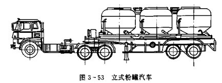
1. The center line of the tank body of the vertical powder tank car vertical powder tank car is vertical, as shown in Figure 3-53. The vehicle can carry one or more vertical tanks. Vertical powder tank cars have a wide range of applications and can be used for the bulk transportation of powder, granular materials, and other powder and granular materials. However, the center of gravity of the entire vehicle is high, and when multiple tanks are used, the structure is complicated and the manufacturing cost is high.
2. The centerline of the horizontal powder tank car body is horizontal. The tank body can be a single tank or two tanks. If the fluidized bed in the tank is at an angle with the horizontal plane, it is called an inward horizontal powder tank brake, as shown in Figure 3-54. If the centerline of the tank body is at a slight angle to the horizontal plane, it is an outward-decanting horizontal powder tank car. The horizontal type powder tank car has the advantages of simple structure, convenient operation, stable unloading performance and low center of mass, but its applicability is limited, and it is generally only used for powder bulk transportation with better fluidization performance. 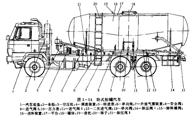
3. Lifting type powder tank car Lifting type powder tank car The center line of the tank body is in a horizontal position during charging and driving. When lifting the material, lift the front end of the tank body to raise the tilted state, as shown in Fig. 3- 55 shows. The bottom of the tank of a lift-type powder tank car is usually provided with a fluidized bed only at the discharge port. The discharge into the tank body is inclined, and the powder particles automatically fall down under the action of gravity and concentrate at the discharge port. Discharged. Therefore, the internal structure of the can body is simple, the volumetric efficiency is high, and the application scope is wide. It is commonly used to load the powder material with poor fluidization performance. However, due to the increase of the lifting mechanism, the use and maintenance are complicated. 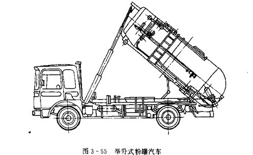
4. The bucket body of the bucket-type powder tank car bucket-type powder tank car is composed of a straight cylinder or a rectangular tube with a horizontal center line and a cone tube vertical to the center line, as shown in Figure 3-56. Bucket-type powder tank cars usually do not have a fluidized bed and are automatically discharged using the gravity of the powder. Therefore, it has a simple structure and a wide range of applications. The remaining amount is small, the tank is easy to clean and so on.
(B) The basic knowledge of powder fluidization
1, powder characteristics 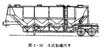
The transportation of bulk powders has a close relationship with the characteristics of powder materials. The main characteristics of the powder are as follows:
(1) Particle size: The shape of the powder particles is irregular, and the surface has grooves, pits or holes, and the particle size is not the same. Generally, the material with a given diameter within a certain range is defined as a granular group, and the average particle size of the granular group is referred to as particle size. The particle size distribution in the powder directly affects the properties of the powder.
(2) Density Density refers to the mass per unit volume of powder, commonly used in units of kg/L3 or t/m3. Because the porosity of the powder (the ratio of the volume of air between the particles to the entire volume, the cement is 0.66) and the particle size distribution are different, it can be further divided into:
1 true density. Refers to the ratio of the mass of the particles to the true volume of all the particles that do not include the voids before the particles on the surface of the particles and the particles.
2 apparent density. Refers to the ratio of the mass of the particles to the volume of all particles not including the voids between the particles.
3 particle density. Refers to the ratio of the mass of a particle to the volume of all particles including the voids between the surface of the particle and the space between the particles.
4 bulk density. Also known as loose density, refers to the ratio of the particle mass to the volume of the container when the particles fill the container. Commonly used are particle density and bulk density.
(3) The angle between the cone-shaped busbar and the bottom surface formed when the angle of repose is in the powder pile is known as the static repose angle; the repose angle formed when the stacking material is also subjected to vibration is called the dynamic repose angle. For the determination of the angle of repose, see Figure 3-57. The size of the repose angle is related to the particle size, internal friction angle, and adhesion of the powder.
(4) Friction Angle The friction angle represents the coefficient of friction between the material and the solid wall. The size of the friction angle is related to the particle size, adhesion, wall material, shape, and surface roughness of the material.
(5) Adhesive Adhesion refers to the phenomenon of adhesion between the powders and between the powder and the wall surface. According to the analysis, the force of adhesion between the particles and the force between the particles and the wall are mainly the attraction between molecules, the electrostatic force and the capillary force of moisture. Adhesion is related to the properties of the powder, moisture, wall materials, and surface roughness.
(6) Moisture Content The moisture of the material includes free water attached to the surface of the particles and chemical water incorporated inside the particles. Chemical water is a component of particles. Free water is the moisture content of the powder, expressed by the moisture content w: 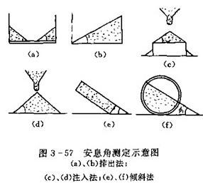
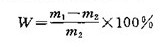
The mass (kg) of the M1----sample before drying in the formula;
M2----The mass (kg) after the sample was dried at a temperature of 105°C for 2-4 h.
2. Suspension velocity and sedimentation velocity of the material Suspension velocity refers to the velocity of the gas stream when the particles of the material are suspended in the vertical plumbing. Suspension speed is the main dynamic performance of the powder, indicating the ease of pneumatic conveying. The suspension speed of the material is generally determined experimentally.
Settling velocity refers to the fact that when the particles of the material fall freely in the still air, due to the action of gravity, the falling velocity gradually increases, and the air resistance of the particles also increases. When the air resistance increases to be equal to the particle's float weight (difference between gravity and air buoyancy), the material particles fall at the same rate as the maximum velocity at that time. This constant rate of fall is called the sedimentation rate of the material particles. Obviously, The material's levitation velocity and sedimentation velocity are equal and opposite.
3. Fluidization of the material Fluidization is the process of introducing a gas into the bed of a particulate material, which results in the bed having some similar liquid characteristics. Fill the container with powder and granular material, and set a ventilation element at the bottom of the material to support the powder. Set the flow rate of the gas through the cross section of the container to u. The actual flow rate of gas through the void of the powder and granular layer is  Obviously,
  <u. With the change of u, the powder bed will appear as shown in Figure 3-58.
(1) Fixed bed When the airflow velocity is small, the air flow passes through the gaps between the particles, the particles do not move, the porosity E of the bed remains unchanged, and the bed maintains the original height, as in the BF section in the figure. The speed of airflow through the bed  And pressure loss
  With the increase of airflow speed, the number increases, as shown in the AF, AF
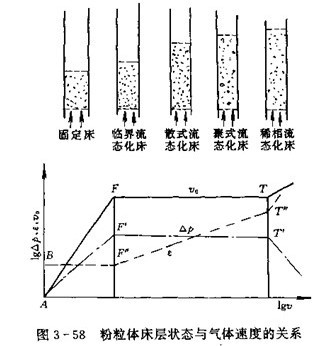
segment. This state of powder is called a fixed bed.
(2) After the critical fluidized bed gas velocity u increases to a certain value, the resistance of the gas flow through the bed is just equal to the weight of the powder on the bed, and the bed begins to expand.  Increase with u, as shown in the figure
  segment. due to
  With the increase, the area of ​​the channel between the powder and the particles also increases, so the actual flow rate u0 of the gas flow through the bed does not increase, as shown in the FT section. Air pressure loss
  Not because of the increase in u needs to increase, as shown in the figure
  At this point, the gravity of the particulates is no longer supported directly by the air-permeable elements below, but by the friction between the gas and the particulates. For each particle, it is no longer maintained by the contact of adjacent particles, and they are free to move in the bed. The pressure drop across any section in the bed is approximately equal to the weight of the powder body on the section, and the height of the bed is
  The increase increases but there is a clear upper interface. The bed begins to produce this varying air velocity,
  The corresponding air flow velocity at the point is called the critical fluidization velocity of the
  Indicated. Table 3-4 lists the critical fluidization rates for some of the granules.
  .
. 
(3) Bulk fluidized bed and poly fluidized bed, if the air velocity ratio  If there is not much, and the powder size is small, the bed of the powder and granular material expands continuously and the average distance between the particles increases. The airflow evenly flows in the bed and becomes a loose fluidized bed, or it can be said to be first-rate. Bed; if the air speed ratio
  Larger and more, excessive gas bubbles in the form of bubbles and then flow through the bed, then become poly-type fluidized bed, or bubble-type fluidized bed, non-homogeneous bed. The bed heights of both fluidized beds have increased, but there is still a clear upper interface.
(4) Dilute phase fluidized bed, when the gas charging rate in the bed increases to the material levitation speed  At the time, the particulates begin to fly out of the upper interface and enter the space above, when the air velocity exceeds
  After that, the particles will be taken out of the container, forming a dilute fluidized bed. At this point, the porosity
  Rapid increase in pressure drop caused by friction loss between particles
  Sharply reduced, the actual formation of solid-gas two-phase composed of powder and gas ------ dilute phase pneumatic conveying state. If this condition occurs in the bed, the unloading cannot be complete. It can be seen that the airflow velocity of a fluidized bed can only be
  with
with  between.
4. The liquid-like fluidized bed material of the fluidized bed powder has some similar properties. As shown in Figure 3-59. Figure 3-59(a) shows that large, light particles are resilient, and that particles can easily return to the bed when they are under pressure; after the pressure is relieved, they bounce back into the space above. Figure 3-59(b) shows the fluidity of the bed. When the vessel is tilted, the upper interface remains horizontal. Figure 3-59(c) shows that particles can be ejected from the side wall orifices. Figure 3-59(d) shows that after the two fluidized beds are connected, the particles can flow from the high bed to the low bed and automatically balance the bed height. Figure 3-59(e) shows that the pressure difference at any two points in the bed is approximately equal to the static pressure at these two points.
The pneumatic unloading of the powder tank car makes use of these characteristics of the fluidized powder for pneumatic conveying.
Sanitary Ware, Bathtub,Bathroom Basin & Sink ,Toilet
Water Manifold,Pipe Clamp Co., Ltd. , http://www.nbpipefittings.com