Hello everyone, today Xisheng Microvision has introduced the issue of antenna calibration for wireless bridge microwave transmission. In microwave communication, for the calibration of the antenna azimuth angle, the traditional method is to adjust the initial horizontal azimuth and elevation angle of the antenna according to the angle of the design requirements, and then the antenna of the two microwave stations alternately turns up and down. Turn left and right to catch the other's signal. One antenna has two angle variables, namely the horizontal angle and the pitch angle. Two antennas between two microwave stations are required to calibrate their azimuth angles. There are 4 independent variables to be calibrated. However, due to the limitations of on-site conditions, the azimuth angles and design requirements adjusted by the theodolite's instructions have a large error, which brings great difficulties to the adjustment work and often takes a day or two to complete.
In the microwave communication engineering practice, we summed up past experience and proposed the "hammer line method." The so-called heavy hammer line method, is in front of the antenna aperture plane, with a thin line to hang a hammer, with the weight line as a baseline, adjust the pitch angle of the antenna, so that the plane of the antenna aperture parallel to the weight line Or coincident, the antenna is perpendicular to the ground plane as the initial pitch angle of the antenna in the vertical direction. Because the weight line is very thin and the plane of the antenna aperture is large, the adjusted antenna verticality error is small. This simplifies the four angular variables to be adjusted for the two antennas to their respective horizontal azimuths.
1 Antenna-antenna system calibration for two microwave stations
After adjusting the antenna of the two microwave stations to the vertical position by means of a weighted hammer method, the vertical position of the antenna is fixed, and the two antennas rotate the respective horizontal azimuth angles back and forth. When the two antennas are turned back and forth, they will cause the two antennas to point Parallel to each other, the microwaves at the two stations appear to receive indications of the other party's signals. At this point, the pitch and horizontal angles of each antenna are fine-tuned again so that the microwave receiver receives the maximum indication, and the calibration of the antenna azimuth angles of the two microwave stations is completed.
2 Antenna-reflector-antenna system calibration for two microwave stations
In the antenna-reflector-antenna system, the reflector also has two adjustable angles, namely pitch and horizontal azimuth. There are a total of six independent variable angle parameters to adjust in this system, which is extremely complicated. The traditional calibration method is based on the requirements of the design. The azimuth angle is used as the initial angle. Then, each time the reflector deflects a small angle, the antenna rotates back and forth, up, down, left, and right, adjusting its pitch and horizontal azimuth. Until the antenna receives the other's signal and fine tune again. Due to the limitation of on-site conditions, the errors of the initial angle and the design angle adjusted by the theodolite according to the design requirements are relatively large. In such a complex system, calibration has brought greater difficulties.
How to simplify the adjustment of complex systems? Use a piecewise adjustment method. The so-called segmentation adjustment method is to divide the antenna A-reflector B-antenna C system into two small systems: the antenna A-reflector B and the reflector B-antenna C. Under the reflector B, use a portable device. The small antenna is connected with a portable high-sensitivity power meter to receive the signal indication instead of the reflector B. In this way, a complex system is decomposed into 2 simple segments of antenna A—small antenna and small antenna—antenna C.
Use hammer line method to adjust long-distance segments, such as antenna A-small antenna segment, use antenna A microwave machine as signal source, small antenna power meter for receiving field strength indication, adjust to the maximum power meter reading indication, ie Antenna A is considered to be aligned with reflector B. For another short-distance small antenna-antenna C segment, the microwave machine of antenna C is used as a signal source, and the power meter of the small antenna is used as a receiving field strength indication. This section is close enough to be seen and easily adjusted. The indication of the reading of the power meter is maximized, that is, the antenna C is aligned with the reflector B. Then adjust the angle of the reflection plate B. The reflection plate starts from the vertical position, and once it leans down at a small angle, it turns one time in the horizontal direction. During the adjustment of the reflector, two antennas, A and C, can receive signals from each other and indicate them on the microwave receiver. Finally, fine-tune antenna A, antenna C, and reflector B. When the microwave receiver indication of both stations reaches the maximum, the horizontal and tilt angles of the entire antenna-reflector-antenna system are calibrated.
3 adjustment examples
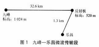
Nine peaks - Lechang microwave transmission section, the middle of the reflector inserted, as shown in Figure 1.
Connect a portable portable antenna with a small diameter of 1.2 m to a portable, highly sensitive power meter with a -65 dB indication and place it under the reflector.
The adjustment procedure is as follows:
a) Adjust Jiufeng-reflector section
Using the microwave transmitter of Jiufeng Station as the signal source, the small antenna below the reflector is connected to the power meter for receiving the field strength indication. Because this section is far away, use the hammer line method to debug. After the power meter reading reaches the maximum, the antenna of Jiufeng station is considered to be aligned with the reflector.
b) Adjust the reflector - Lechang Station
Because this segment is close enough, you can see each other with your eyes, so adjustments are easy. Use the microwave transmitter at Lechang Station as the signal source (in this case, the signal of the microwave transmitter of Jiufeng Station should be turned off to prevent the small antenna from receiving signals from Jiufeng Station to interfere with the reading of the power meter). The small antenna below the board is connected to the power meter for receiving field strength indication. Adjust the two antennas. After the power meter reading indication reaches the maximum, the Lechang station antenna is considered to be aligned with the reflector.
c) Adjust the reflector angle
The microwave transceivers at Jiufeng Station and Lechang Station are used as signal sources and receiving field strength indications.
The reflection plate starts from the vertical position, and it rotates one time back and forth in the horizontal direction every time it leans down at a small angle. Because in the last two steps, the antennas of Jiufeng and Lechang Stations are all aligned with the reflectors. During the adjustment process, when the reflectors bow to a certain position, the Jiufeng and Lechang microwave receivers can Indicates that the other party's signal was received. When the receiving signals of the microwave receivers on both sides reach the maximum, the pitch and horizontal azimuth angles of the reflectors are initially adjusted.
d) System fine-tuning
After the first three steps are completed, the pitch and horizontal angles of the Jiufeng station antenna, Lechang station antenna, and reflector are adjusted one by one until the microwave receivers at the two stations indicate the maximum. The level and pitch angle of the entire system are calibrated. This step is necessary, fine tuning under large signals can improve the accuracy of the angle adjustment.
4 Discussion
Considering the characteristics of the main lobe of the antenna pattern, the main lobe characteristic shows the distribution of the field intensity in the main communication direction. The half-power angle is half the power value of the electromagnetic field power change on both sides of the main lobe in the direction of maximum radiation ( That is, the angle at 3 dB).
Two microwave stations are located 40 km apart and both use a 3 m diameter parabolic antenna with a half power angle of 0.8°. 40 000 m×sin0.8°=528 m, indicating that when the elevation difference between the two antennas is within 528 m, they are within the half-power angle of the other antenna and can receive the signal from the other antenna well. . The half power angle of a 3 m diameter parabolic antenna is 0.8°, the half power angle of a 2 m diameter parabolic antenna is 1.5°, and the half power angle of a 1.2 m diameter parabolic antenna is 3°. Therefore, the vertical position of the antenna can be handled as the initial pitch angle of the antenna, so that the four independent variable angles of the two antennas are reduced to a two-variable system with a horizontal azimuth angle only.
I believe that through the above article, we have a new understanding of the antenna in wireless transmission. The stability of transmission is not only related to the wireless bridge equipment, but also the adjustment of the antenna is also very important. Xisheng Microvision Corporation focuses on wireless video transmission. The R&D and production of equipment has a wealth of wireless experience. Xisheng Microview has mastered wireless technology.
Electric Stacker:
We manufacture Compact Electric Stacker and full
electric Stacker for market demands. Our Narrow Aisle Electric Stacker has side-driven design and
maintenance free battery. It is a great walk
behind forklift. Our straddle
electric stacker is our client`s favorite. This ride-on electric stacker has AC brushless motor which provides more
power and less maintenance required. Akodi also supplies best value counterbalance electric forklift.
Economical
electric stacker:
-
High-power, high-performance lift
motor: powerful cargo lifting, cost-effective
-
DC motor drive system: smaller size,
high efficiency
-
Side-driven design: smaller turning
radius, suitable for operation in confined space
-
Operation handle: ergonomics,
comfortable operation, increased work efficiency
-
Maintenance free battery and internal
charger: easy for maintenance, easy to charge
-
Optional: Adjustable baseleg

|
Measurement/
Model
|
CL-10
|
|
Capacity
(Q)
|
kg
|
1000
|
|
Load
Center (C )
|
mm
|
500
|
|
Max
lift height (h)
|
mm
|
2000/2500/3000
|
|
Overall
extended height
|
mm
|
2415/2915/3415
|
|
Overall
collapsed height
|
mm
|
1580/1830/2080
|
|
Overall
fork width (b2)
|
mm
|
540/680
|
|
Fork
size (L*W*T)
|
mm
|
1150
(1220)*160*55
|
|
Min
height (h1)
|
mm
|
90
|
|
Overall
width (b1)
|
mm
|
820
|
|
Overall
length (L)
|
mm
|
1950
(2020)
|
|
Turning
radius (Wr)
|
mm
|
1360
|
|
Max
travel speed, full load/no load
|
Km/h
|
3/4.5
|
|
Max
lift speed, full load/ no load
|
mm/s
|
80/100
|
|
Max
lowering speed, full load/no load
|
mm/s
|
90/120
|
|
Max
Gradient performance, full load/ no load
|
%
|
5/7
|
|
Rear
drive wheel
|
mm
|
PU
φ210*70
|
|
Front
wheel
|
mm
|
PA/PU
φ80*70
|
|
Balance
wheel
|
mm
|
PA/PU
φ180*50
|
|
Driving
motor
|
Kw
|
DC0.75
|
|
Lift
motor
|
Kw
|
DC1.5
|
|
Battery
capacity
|
V/A
|
12V*2/60Ah
|
|
Weight
|
Kg
|
440/490/535
|
|
Battery
weight
|
Kg
|
45
|
Full electric
stacker:
-
Curtis control system and brushless
AC drive motor: powerful, improved work efficiency, and reliability
-
Forklift mast wheel, sprocket, chain,
and bearings: increased work efficiency, eliminating costly repair
-
Operation handle: ergonomics, comfortable
operation, increased work efficiency, break override feature
-
High quality protective glass:
exceptional visibility, ensures operator`s safety
-
Electronic steering: experiences less
fatigue, more accurate control
-
Optional: mechanical steering, adjustable
baseleg, shock-absorbing platform

|
Measurement/
Model
|
CL-10
|
CL-12
|
CL-15
|
|
Capacity
(Q)
|
kg
|
1000
|
1200
|
1500
|
|
Max
height (h)
|
mm
|
1600/2600/3200/3600
|
1600/2600/3200/3600
|
1600/2600/3200/3600
|
|
Overall
fork width (b2)
|
mm
|
570/690
|
570/690
|
570/690
|
|
Fork
size
|
mm
|
1150
|
1150
|
1150
|
|
Min
height (h1)
|
mm
|
86
|
86
|
86
|
|
Overall
height (h4)
|
mm
|
2000/1800/2100/2350
|
2000/1800/2100/2350
|
2000/1800/2100/2350
|
|
Overall
width (b1)
|
mm
|
805
|
805
|
805
|
|
Overall
length (L)
|
mm
|
1865
|
1865
|
1865
|
|
Turning
radius (wr)
|
mm
|
1436
|
1436
|
1436
|
|
Load
center (C )
|
mm
|
600
|
600
|
600
|
|
Battery
capacity
|
V/A
|
210Ah/24V
|
210Ah/24V
|
210Ah/24V
|
|
Charger
|
|
24V/30A
|
24V/30A
|
24V/30A
|
|
Weight
|
Kg
|
817-927
|
827-937
|
827-937
|
|
Battery
weight
|
Kg
|
175
|
175
|
175
|
Electric Stacker
Compact Electric Stacker,Full Electric Stacker,Narrow Aisle Electric Stacker,Walk Behind Forklift
Akodi Intelligent Robot Technology Co., LTD , https://www.akodiforklift.com